Intel PMU
There are a finite number of performance event select MSRs (IA32_PERFEVTSELx MSRs).
The result of a performance monitoring event is reported in a performance monitoring counter (IA32_PMCx MSR).
두 register는 아래의 사항을 따른다.
- IA32_PERFEVTSELx의 bit field layout은 모든 microarchitecture들이 동일하다.
- IA32_PERFEVTSELx MSRs의 주소와 IA32_PMC MSRs의 주소는 모든 microarchitecture들이 동일하다.
- 모든 logical processor는 IA32_PERFEVTSELx 와 IA32_PMCx MSR들을 각각 가지고 있다. Processor core가 같아도 logical processor의 configuration과 counter는 공유되지 않는다.
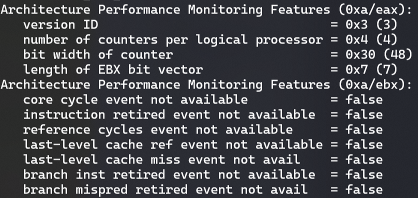
Architectural performance monitoring은 아래의 정보를 나열하기 위해 CPUID mechanism을 제공한다.
- Logical processor에서 사용가능한 performance monitoring counter의 개수
- 각 IA32_PMCx에 지원되는 bit의 개수
- logical processor에서 지원되는 architectural performance monitoring 의 개수
소프트웨어에서 CPUID(CPUID.0AH)를 사용하여 architectural performance monitoring이 가능한지를 알 수 있다. Architectural peformance monitoring leaf는 processor에서 사용가능한 architectural performance monitoring version number를 제공한다. Version은 CPUID.0AH:EAX[bits 7:0]을 쿼리하여 알 수 있다. Version이 0보다 크다면, architectural performance monitoring capability가 제공된다. 소프트웨어가 버전을 알기위해 CPUID.0AH.EAX를 먼저 쿼리하고, CPUID.0AH.EBX에서 사용가능한 기능을 확인한다. 이러한 초기화 과정에서 소프트웨어는 core 당 IA32_PERFEVTSELx/ IA32_PMCx MSR pairs의 개수와 PMC의 bit-width 그리고 가능한 architectural performance monitoring event의 개수를 알 수 있다.

Architectural performance monitoring facilities include a set of performance monitoring counters and performance
event select registers. These MSRs have the following properties:
- IA32_PMCx MSRs은 0C1H 주소값으로 시작하고, 각 logical process의 MSR 개수만큼 연속적으로 이어져있다. MSR 개수는 CPUID.0AH:EAX[15:8]에서 확인할 수 있다.
- IA32_PERFEVTSELx MSRs은 186H로 시작하고 IA32_PMCx MSRs와 개수가 같고 pair한 관계이다.
- IA32_PMCx MSR의 bit width는 CPUID.0AH:EAX[23:16]에서 확인할 수 있으며 이는 read operation에 사용되는 valid bit의 개수이다. write operation은 MSR의 하위 32bit이고, 어떠한 값이 write 될 수 있다. 그리고 상위 bit의 31bit 값에서 부호를 결정한다.
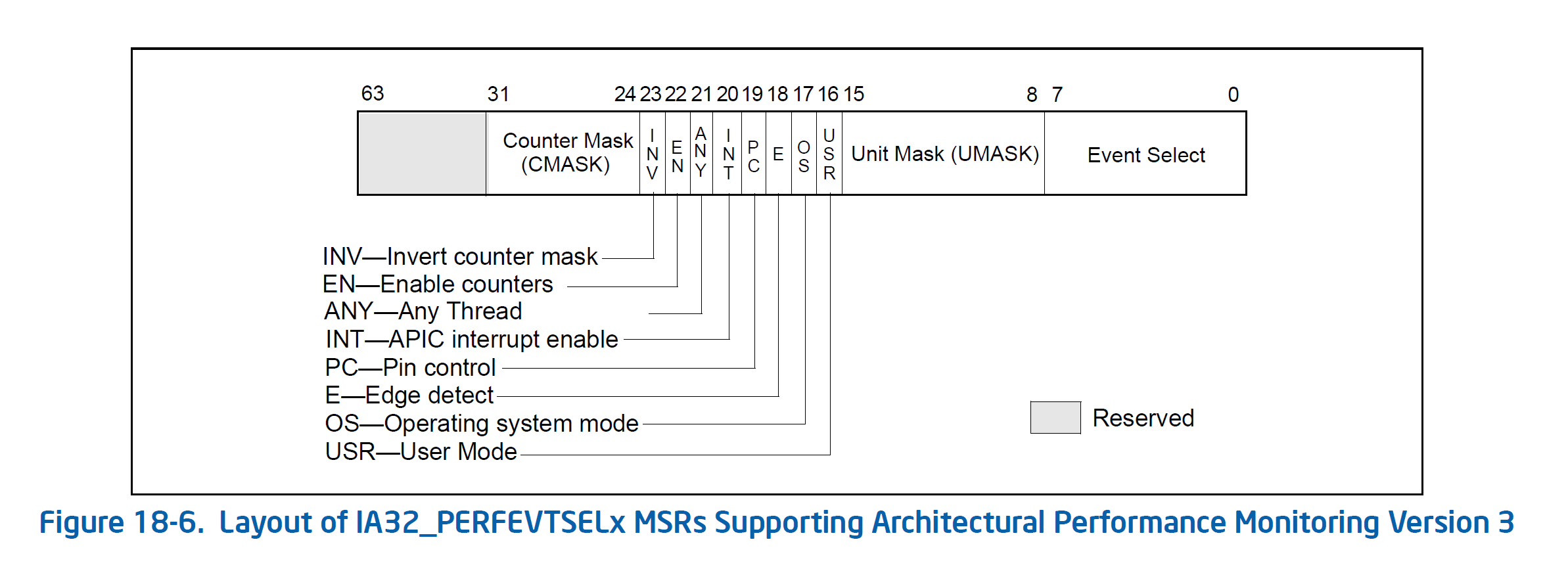
See Figure 18-1 for the bit field layout of IA32_PERFEVTSELx MSRs. The bit fields are:

- Event select filed (bit 0~7): microarchitectural condition을 감지하는데 사용되는 event logic unit을 선택한다(see Table 18-1, for a list of architectural events and their 8-bit codes). 이 field의 값은 architecturally 하게 정의돤다. 각 값은 architectural performance event를 사용하기 위한 event logic unit과 같다. Architectural event의 수는 CPUID.0AH:EAX에서 볼 수 있다. Processor는 pre-defined value만 사용할 수 있다.
- Unit mask (UMASK) field (bits 8~15): 이 bit들은 selected event logic unit이 감지하는 조건을 규정한다. 각 event logic unit에 대한 유효한 UMASK 값은 unit에 따라 다르다. 각 architectural performance event에 대해 UMASK 값은 특정 microarchitecture condition을 정의한다.
- Architectural event와 관련된 pre-defined microarchitectural condition은 주어진 processor에서 사용하지 못할 수 있고 pre-defined architectural event만 사용가능 하다. Pre-defined architectural event는 Table 18-1에 나열되어 d있다. 지원되는 pre-defined architectural event는 CPUID.0AH:EBX를 보고 알 수 있다. 초기 구현에서 사용할 수있는 architectural performance event는 Table 19-1에 나열되어 있다.
- USR (user mode) flag (bit 16) — Specifies that the selected microarchitectural condition is counted when the logical processor is operating at privilege levels 1, 2 or 3. This flag can be used with the OS flag.
- OS (operating system mode) flag (bit 17) — Specifies that the selected microarchitectural condition is counted when the logical processor is operating at privilege level 0. This flag can be used with the USR flag.
- E (edge detect) flag (bit 18) — Enables (when set) edge detection of the selected microarchitectural condition. The logical processor counts the number of deasserted to asserted transitions for any condition that can be expressed by the other fields. The mechanism does not permit back-to-ack assertions to be distinguished. This mechanism allows software to measure not only the fraction of time spent in a particular state, but also the average length of time spent in such a state (for example, the time spent waiting for an interrupt to be serviced).
- PC (pin control) flag (bit 19) — When set, the logical processor toggles the PMi pins and increments the counter when performance-monitoring events occur; when clear, the processor toggles the PMi pins when the counter overflows. The toggling of a pin is defined as assertion of the pin for a single bus clock followed by deassertion.
- INT (APIC interrupt enable) flag (bit 20) — When set, the logical processor generates an exception through its local APIC on counter overflow.
- EN (Enable Counters) Flag (bit 22) — When set, performance counting is enabled in the corresponding performance-monitoring counter; when clear, the corresponding counter is disabled. The event logic unit for a UMASK must be disabled by setting IA32_PERFEVTSELx[bit 22] = 0, before writing to IA32_PMCx.
- INV (invert) flag (bit 23) — When set, inverts the counter-mask (CMASK) comparison, so that both greater than or equal to and less than comparisons can be made (0: greater than or equal; 1: less than). Note if counter-mask is programmed to zero, INV flag is ignored.
- Counter mask (CMASK) field (bits 24 through 31) — When this field is not zero, a logical processor compares this mask to the events count of the detected microarchitectural condition during a single cycle. If the event count is greater than or equal to this mask, the counter is incremented by one. Otherwise the counter is not incremented. This mask is intended for software to characterize microarchitectural conditions that can count multiple occurrences per cycle (for example, two or more instructions retired per clock; or bus queue occupations). If the counter-mask field is 0, then the counter is incremented each cycle by the event count associated with multiple occurrences.
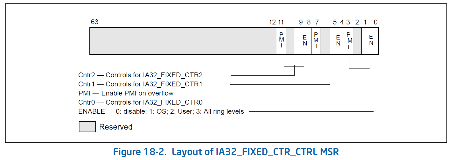
- Architectural Performance Monitoring Version 1

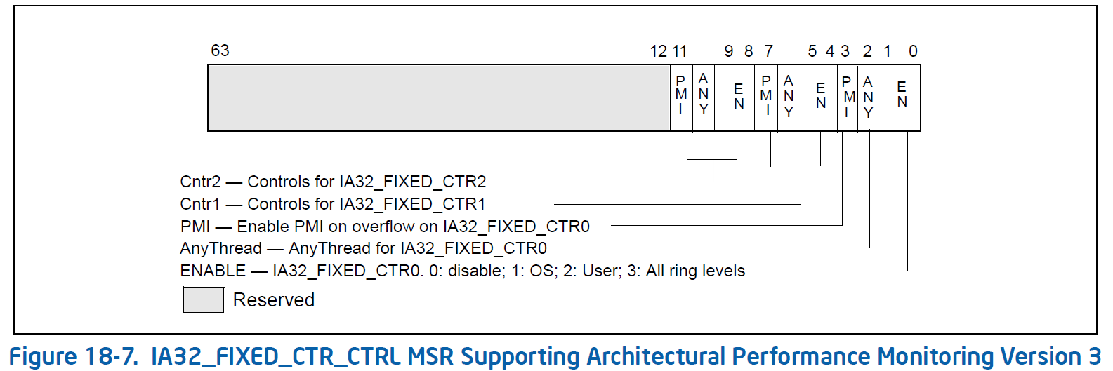
- Architectural Performance Monitoring Version 3

